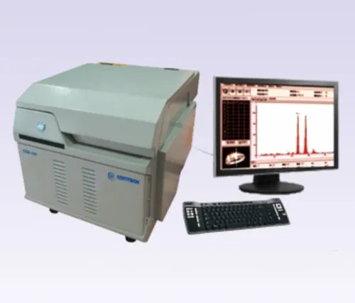

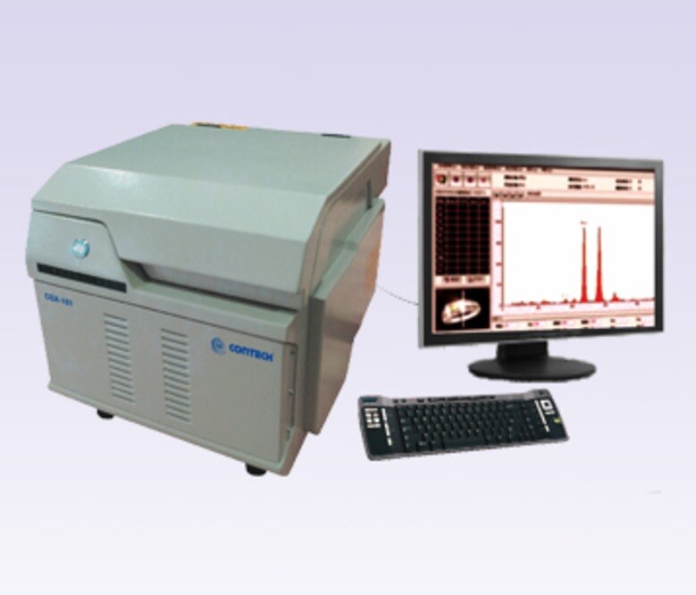
An XRF detector identifies elements in a contact, connector, coating, or alloy, but it does not prove continuity or contact resistance. You will be able to match detector characteristics to the application, separate coating measurements from bulk-alloy readings, and build a test procedure that produces defensible results.
Key takeaways
- Choose silicon-PIN when closely spaced element peaks need clearer separation.
- Choose gas proportional detection when large-area sensitivity and stable throughput matter.
- Clean and position contacts consistently to avoid contamination and geometry errors.
- Compare detector resolution, calibration, maintenance, and coating measurement limits before buying.
What Each Detector Measures—and What Electrical Testing Requires
Inside a gas proportional detector, incoming X-rays ionise an argon–methane fill gas. The released electrons multiply under high voltage, producing a charge pulse whose size corresponds to photon energy; pulse processing sorts those pulses into an X-ray spectrum. A gas-tight window, stable gas flow, gas purity, and leak-free plumbing therefore affect operation.
A Silicon-PIN detector uses silicon instead. Each X-ray creates electron–hole pairs in the semiconductor, and collected charge becomes a pulse for energy analysis. It needs bias voltage and control of leakage current and electronic noise, but no detector-gas supply.
| Detector | Physical signal process | Practical implication |
|---|---|---|
| Gas proportional | Gas ionisation and electron avalanche | Large-area, low-energy response; gas flow, window condition, and leaks require attention |
| Silicon-PIN | Electron–hole pairs collected in silicon | No detector gas; entrance-window thickness, bias, noise, and cooling affect performance |
An electrical testing gas proportional XRF detector still measures characteristic X-ray intensities to infer elements such as gold, silver, copper, nickel, and zinc. It does not measure conductivity. Electrical testing of a connector or contact requires a separate continuity, bulk-resistivity, or contact-resistance instrument, such as a four-wire Kelvin setup.
XRF also cannot replace insulation-resistance or high-voltage safety tests. For gold, compact systems normally use Au L lines; Au K lines near 69–78 keV require excitation above the roughly 11.9 keV Au L3 edge and are outside ordinary low-voltage tube operation.
Gas Proportional or Silicon-PIN: Which Signals Are Easier to Separate?
A Silicon-PIN detector separates nearby lines more clearly: at the 5.9 keV Mn K-alpha line, its typical 0.15–0.25 keV FWHM resolution is much sharper than the 0.8–1.2 keV common for a gas proportional counter. That difference matters when a gold analyzer must distinguish Au L-alpha near 9.71 keV from Pt L-alpha near 9.44 keV.
| Factor | Gas proportional | Silicon-PIN |
|---|---|---|
| Energy resolution | Broader peaks; overlapping alloy lines rely more on spectral fitting and standards. | Sharper peaks improve separation of Au, Pt, Ni, Cu, and Zn lines. |
| Sensitivity | Large area and thin windows can give strong low-energy response. | Depends heavily on detector area and entrance-window thickness. |
| Count-rate handling | Compare usable throughput at the specified dead-time limit; pile-up still distorts peaks. | Fast pulse processing can support high rates, but pile-up and pulse rejection still require control. |
| Dead time | Rising dead time reduces effective counts and can bias results. | The same risk applies; record dead time with every measurement. |
| Stability | Requires detector-gas management and stable operating conditions. | No gas logistics, but leakage current and noise rise with temperature. |
| Repeatability | Good geometry and gas control are essential. | Temperature stabilisation improves long-term peak position and repeatability. |
| Detection limits | Low-energy efficiency and large area can help trace-element detection. | Better separation can lower practical limits when interference dominates. |
For electrical testing machines, neither detector fixes poor sample geometry, unsuitable tube voltage, or a mismatched calibration. Specify the window, distance, take-off angle, dead-time range, and detection limits using your actual contact or plating matrix.
Choosing a Method for Gold, Silver, Copper, and Contact Platings
A gold-plated base-metal object can produce a high apparent-gold result because XRF weights the surface more heavily than the interior. Before buying gold testing equipment or a gold analyzer, confirm whether it reports bulk composition, coating thickness, or only calibrated apparent alloy composition; those are different measurements.
| Item | Use a bulk-alloy method when | Use a coating-thickness method when |
|---|---|---|
| Jewellery | You need gold, silver, copper, or other alloy content in a homogeneous solid item. | You need to verify gold, silver, rhodium, or other plating over nickel, copper, or base metal. |
| Bullion | You are checking fineness through a substantial, uniform metal surface. | You suspect plating, cladding, or a deceptive surface. |
| Connectors | You are identifying the copper, brass, or other bulk body alloy. | You are measuring gold, nickel, tin, or palladium on the mating surface. |
| Switch contacts | You need the contact material’s bulk composition. | You need plating thickness that controls wear, resistance, and service life. |
| Circuit boards | You are screening solder, copper traces, or component alloy content. | You are checking plated through-holes, edge fingers, or connector finishes. |
| Cable coatings | The cable has a metallic sheath or conductor whose alloy matters. | A metallic coating’s thickness matters; XRF does not replace insulation or continuity tests. |
| Electronic parts | You are identifying a package, lead, or termination alloy. | You are verifying a specified finish on leads, pads, or contact areas. |
Use the coating method when the surface layer is the product requirement. Use bulk analysis when the object is a uniform alloy. An XRF result never proves resistance, continuity, or contact performance; pair it with the appropriate electrical test.
How to Measure a Contact Without Creating a False Result
A small, curved contact can produce a false result before the detector has made a mistake. Keep the X-ray spot entirely on the contact, hold the surface at the calibrated working distance, and treat every reading as a measurement of the illuminated volume—not automatically of the whole part.
1. Secure the contact so it cannot tilt, and use a fixture or collimator that fits the available area. For curved contacts, take readings at several positions and orientations; a beam partly hitting the substrate or neighbouring metal changes the apparent composition.
2. Clean grease, fingerprints, flux and dust with a documented solvent that will not dissolve the plating. Remove loose oxide, but do not polish away the production surface unless the test method specifies it. Roughness changes the beam angle and coating path length, so repeat measurements on the flattest area.
3. Keep solder joints, welds and exposed base metal outside the spot. Solder can add tin, lead or silver, while an oxide or contaminated film can alter a thin coating result. Mark the tested location.
4. Treat mixed materials as separate populations. Measure the contact, solder, lead frame and substrate independently; do not average them into one “alloy” result. For a plated part, request coating thickness or layer analysis rather than accepting apparent bulk composition.
5. Watch live count rate and dead time on the testing machines. If the rate is excessive, increase distance, reduce tube current, use an attenuator or narrow the aperture. Pulse pile-up can create false high-energy peaks, and gas proportional detectors can lose gain; repeat the reading after correction.
6. Compare replicate readings with a known reference coupon, then perform separate electrical testing, such as a four-wire Kelvin contact-resistance test. XRF cannot prove continuity or contact performance.
What to Compare Before Buying an XRF System for Electrical Parts
Ask the supplier for detector window material and thickness, active area, FWHM resolution, count-rate limit, dead-time behaviour, detection limits, and sample-to-detector distance. Detector type alone does not predict performance.
| Option | Request | Selection consequence |
|---|---|---|
| Gas proportional | Thin entrance window; 0.8–1.2 keV FWHM at Mn K-alpha (5.9 keV); gas type, flow and high-voltage requirements | Strong low-energy response and large area, but broader peaks and gas maintenance |
| Silicon-PIN | Window thickness; 0.15–0.25 keV FWHM at Mn K-alpha; maximum count rate and dead-time correction | Cleaner peak separation and simpler operation; a thick window can reduce sensitivity below a few keV |
| Either detector | Tube target, voltage, current, filters, spot size, take-off angle and working distance | Geometry and excitation can outweigh detector choice |
For gold testing, confirm that the tube excites Au L lines. The Au L3 edge is about 11.9 keV; Au K lines near 69–78 keV require far higher excitation. A conventional tube below that K-edge cannot produce Au K-line excitation.
Request application-specific calibration standards for gold, silver, copper, nickel, zinc and palladium, including plating thickness and substrate matrices. Demand raw spectra, uncertainty, repeatability data, reference-material certificates, software revision history and calibration intervals.
- Ask whether the instrument measures curved contacts, small spots and multilayer coatings.
- Confirm gas purity, flow-rate checks, leak testing and window replacement for a gas system.
- Confirm detector cleaning, tube life, preventive-maintenance intervals and service response.
- Remember that an electrical testing gas proportional XRF detector measures composition, not continuity or contact resistance; use a four-wire Kelvin test separately.
CONTECH INSTRUMENTS LTD. should state these specifications for each configuration rather than leaving buyers to infer them from detector names.
Related products
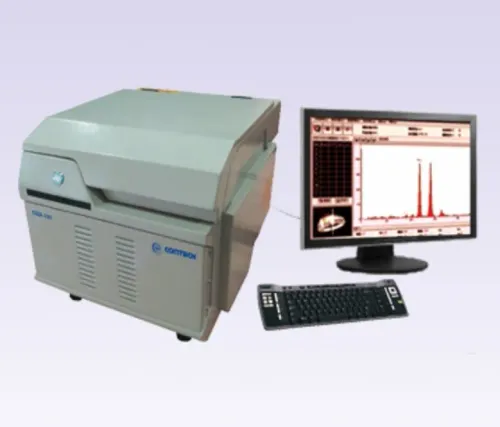
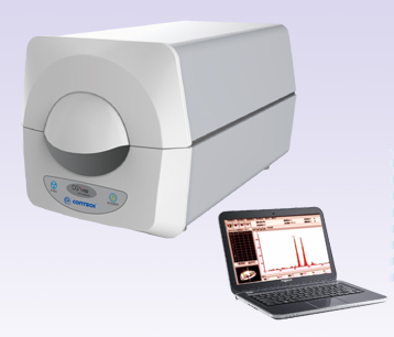 | X-RAY FLUORESCENCE SPECTROMETERS X-Ray Fluorescence Spectrometer – Gas Proportional XRF Detector CGX-101 / Silicon-PIN XRF Detector C GOLD PURITY CHECKING INSTRUMENTS X-Ray Fluorescence Spectrometer – Gas Proportional XRF Detector CGX-101 / Silicon-PIN XRF Detector CGX-102 X-Ray... View product → |
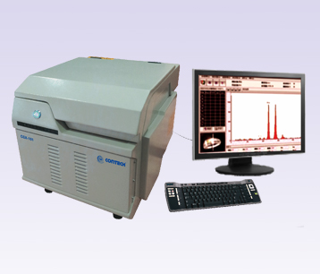 | X-RAY FLUORESCENCE SPECTROMETERS X-Ray Fluorescence Spectrometer – Gas Proportional XRF Detector CGX-101 X-Ray Fluorescence Spectrometer – Gas Proportional XRF Detector CGX-101 The X-Ray Fluorescence Spectrometer – Gas Proportional XRF Detector CGX-101... View product → |
Frequently asked questions
What does a gas proportional XRF detector measure in electrical testing?
It measures characteristic X-rays emitted by the tested material. Argon–methane gas amplifies the signal, and pulse processing sorts photon energies into an elemental spectrum.
Is gas proportional or silicon-PIN easier for separating signals?
Silicon-PIN detectors generally provide sharper energy resolution, making closely spaced elemental peaks easier to distinguish. Gas proportional detectors can provide strong sensitivity but require attention to gas flow, purity, window condition, and leaks.
Which XRF method suits gold, silver, copper, and contact platings?
Choose based on coating thickness, substrate composition, peak overlap, required detection limits, and measurement geometry. Confirm that the analyser’s calibration covers the plating stack you need to test.
How do you measure an electrical contact without creating a false result?
Clean the contact without removing its plating, place it flat and consistently, measure a representative area, and keep the instrument’s aperture clear. Record the part location, coating stack, and measurement conditions.
What should you compare before buying XRF equipment for electrical parts?
Compare detector resolution, coating thickness range, elemental range, spot size, calibration options, repeatability, maintenance requirements, sample positioning, and reporting controls.
Related product
 | LABORATORY BALANCES Semi Micro Balances (CAI Series) (0.00001 g to 60 g) Semi Micro Balances (CAI Series) (0.00001 g to 60 g) The CONTECH Semi Micro Balances (CAI Series) are ultra-high precision laboratory weighing... View product → |